
LIO-SAM 실습해보기 (2)
들어가면서.
LiDAR SLAM에서 가장 기본되는 알고리즘인 LIO-SAM을 공부해보자.
LiDAR Inertial Odometry via Smoothing And Mapping을 줄여서 LIO-SAM이라 한다. LiDAR가 가장 널리 쓰이는 센서로 정착되고, IMU의 사용이 쉬워짐과 동시에, 이런 다른 타입의 센서들을 Factor Graph로 통합하여 Map을 그리는 방식이 가장 흔하기 때문이다. 방 하나정도 공간에 대한 SLAM은 이 이전의 EKF나 PF 기반의 알고리즘과 마이컴 수준으로도 가능했지만 공간이 점점 커짐에 따라 다루어야 하는 메모리도 커지게 되고, 이를 대응하기 위에 여러 센서들을 적용하려면 결국 그래프방식을 쓸수밖에 없는 논리로 흘러가게 된다. 이 후 Loop Closing을 위한 기법들이 더 추가되는 것외에 기본적으로 Lio-SAM은 가장 먼저 적용해볼 수 있는 SLAM 알고리즘이다.
이 글에선 이론적인것은 일단 배제하고 실습중심으로 학습해나가볼까 한다.
그래도 필요한 경우 중간중간 논문을 인용해가면서 진행해보겠다.
학습 순서.
다음과 같은 순서로 최대한 스피디하게 진행해볼까 한다.
- ROS2에 설치해보기
- IMU/PointCloud 다뤄보기 <-여기다
- 데이터셋을 이용하여 LIO-SAM 구현해보기
- 라즈베리파이에 실제 센서 연결해보기.
딱히 알려주는 사람이 없어서, ChatGPT를 활용하여 실습을 진행해본다.
Day 2. IMU/PointCloud 다뤄보기
오늘 다뤄보고자 하는 내용은 상세한 코드의 흐름이다.
- LiDAR, IMU, GPS 데이터가 LIO-SAM 내부에서 어떤 순서로 처리되는가
- imageProjection, featureExtraction, imuPreintegration, mapOptimization 노드의 역할
- LiDAR 좌표계, IMU 좌표계, 베이스 좌표계 사이의 외부 파라미터가 왜 중요한가
- 한 프레임의 포인트클라우드가 deskew, feature extraction, scan-to-map optimization을 거쳐 자세 추정에 사용되는 흐름을 이해한다
- RViz와 ROS 토픽을 이용해 각 처리 단계가 정상인지 확인한다.
- 실행 오류가 발생했을 때 토픽, 시간 동기화, 좌표계, 파라미터 순서로 원인을 좁힐 수 있다.
Test Dataset
우선 동작 확인을 위한 가벼운 데이터셋을 이용하고자 한다.
원저자가 공개하고 있는 간단한 데이터셋들은 구글드라이브에 공개되어있다. Google Drive
여기서 walking_dataset.bag, rotation_dataset.bag을 이용하려 한다. 그 외의 Sample 데이터셋은 LIO-SAM Sample을 확인해보자.
이때의 데이터들은 ROS1용이므로, ROS2용으로 변환해야 한다. 변환용 툴인 rosbags를 설치하고 변환해보자.
python3 -m pip install --user rosbags
rosbags-convert \
  --src walking_dataset.bag \
  --dst walking_dataset_ros2 \
  --src-typestore ros1_noetic \
  --dst-typestore ros2_humble \
  --dst-storage sqlite3 \
  --dst-version 8
변환 후 폴더로 이동해서 확인해보면 다음과 같이 뜰것이다.
~/lio_ws/dataset/walking_dataset_ros2$ ros2 bag info walking_dataset_ros2.db3
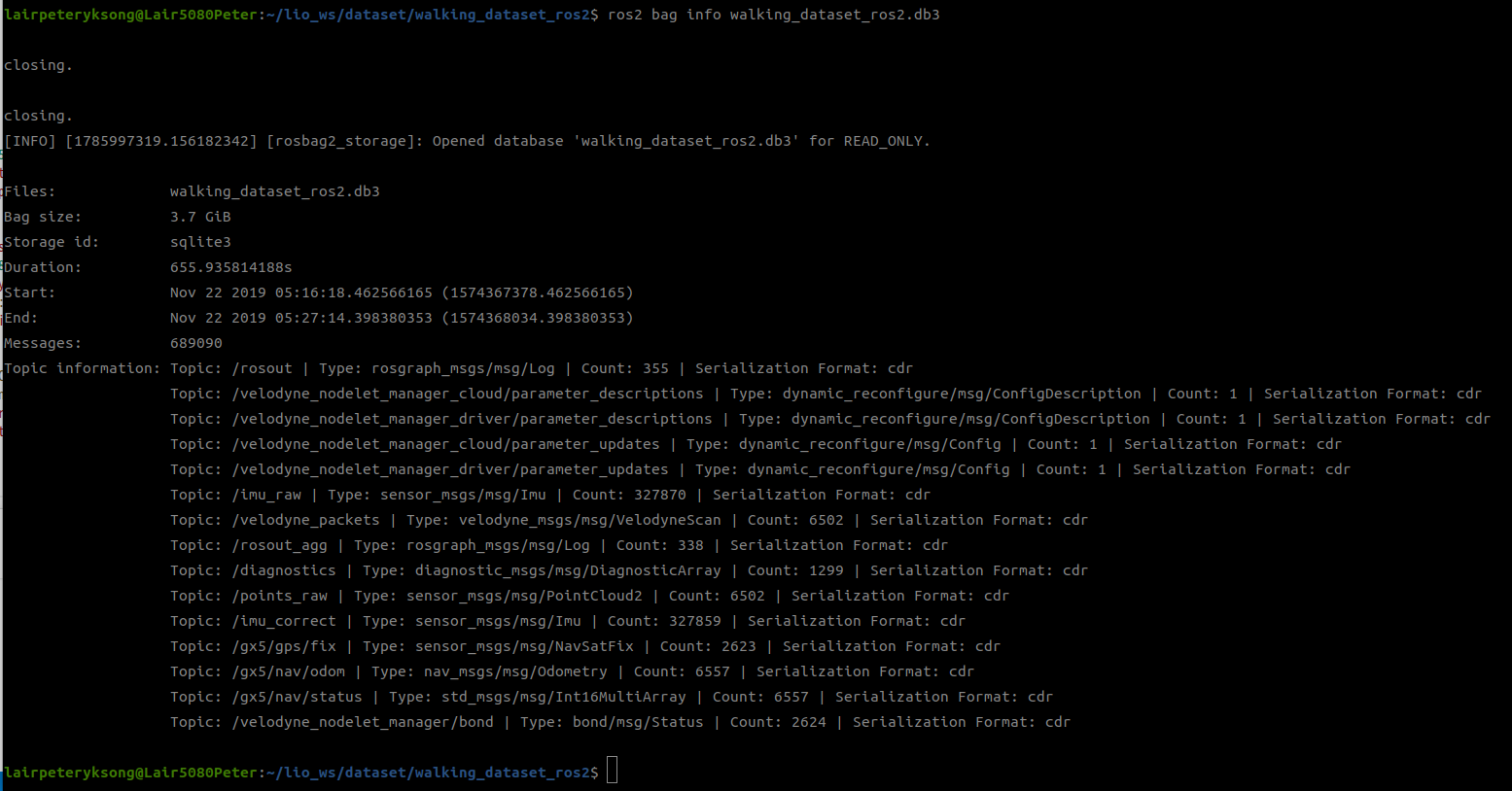
센서 데이터의 숫자만 보면 대략적인 데이터 주기도 알수 있다. 녹화 시간은 2019년 11월 22일 5시 16분부터 5시 27분까지 약 10분간(정확히 10분 56초)인인데 /point_raw의 메세지 수가 6502개이니, 약 9.9Hz정도, /imu_raw 는 327870개이므로 약 500Hz(좋은거 쓰네), 추가로 gps는 2623개의 데이터이므로 약 4Hz정도 된다고 볼 수 있다.
이제 터미널을 띄워보자.
- roscore용 터미널
- rosbag 재생용 터미널
Terminal 1
~/lio_ws/dataset$ ros2 bag play walking_dataset_ros2 --clock
Terminal 2
ros2 topic hz /points_raw
두 창에서 별도로 실행시켜보면 다음과 같이 뜨는걸 볼 수 있다.
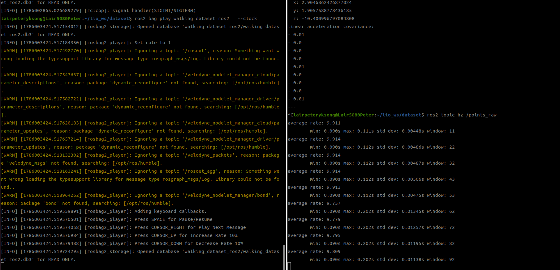
rviz에서 보려면, 다른 터미널에서 rviz2를 실행시키면 된다. 다만, 왼쪽 상단의 “Global Options”에서 Fixed frame을 velodyne으로 수정해주고, 아래쪽 “Add버튼을 눌러 Pointcloud2 를 추가해주면 아래 그림처럼 보인다.
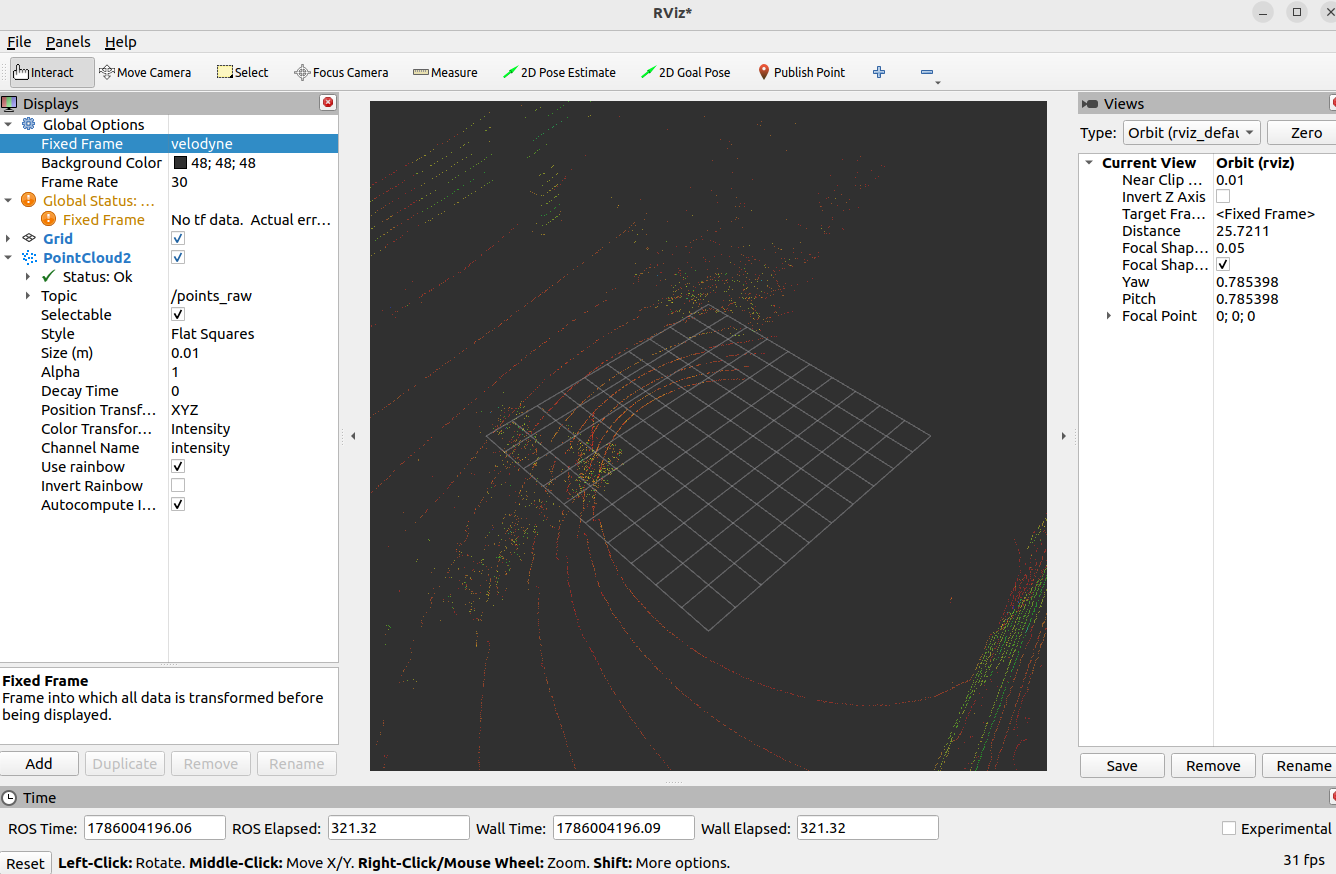
자… 이제 실험용 데이터셋트는 확인했다. 뭔가 우여곡절은 있지만. 데이터셋이 정상임을 확인했으면, 지난번에 배운대로, params.yaml을 수정해서 walking dataset에 맞춰야 한다.
/**:
  ros__parameters:

    # Topics
    pointCloudTopic: "/points_raw"
    imuTopic: "/imu_raw"
    odomTopic: "/gx5/nav/odom"
    gpsTopic: "/gx5/gps/fix"

    # Sensor
    sensor: velodyne
    N_SCAN: 16
    Horizon_SCAN: 1800
    downsampleRate: 1

    # Frames
    lidarFrame: "velodyne"
    baselinkFrame: "base_link"
    odometryFrame: "odom"
    mapFrame: "map"
이제 동작을 일단 확인해보자.
터미널 1 - LIO-SAM
source /opt/ros/humble/setup.bash
source ~/lio_ws/install/setup.bash

ros2 launch lio_sam run.launch.py
아마 rviz가 자동으로 떠 있을거다
터미널 2 - 데이터셋 재생 (Walking dataset)
source /opt/ros/humble/setup.bash
cd ~/lio_ws/dataset

ros2 bag play walking_dataset_ros2 --clock
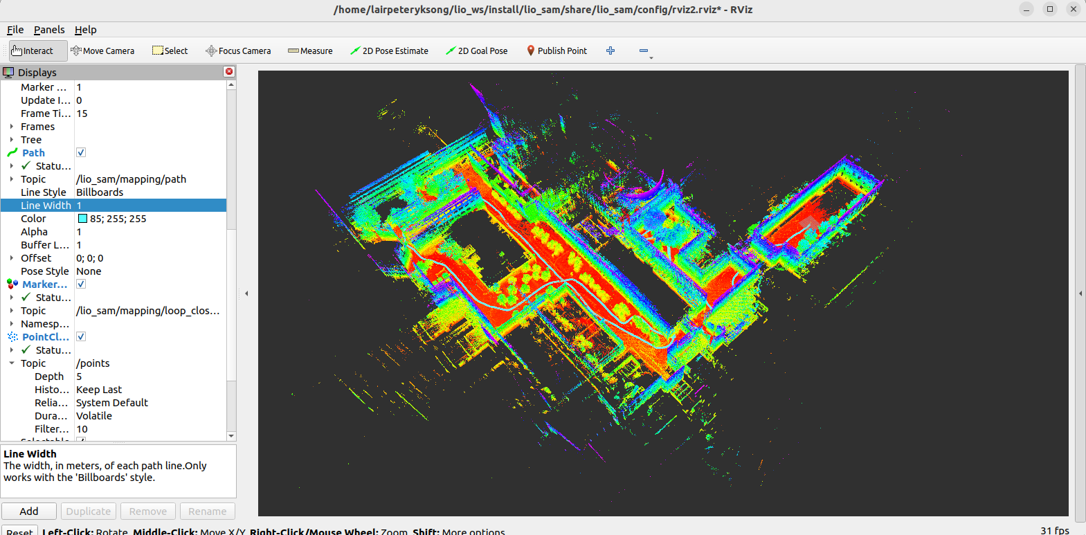
10여분간의 데이터셋 재생이 끝나면 아래 이미지처럼 보일 것이다. trajectory도 보이고, map을 움직여보면 loop detection도 보인다.
이 돌아가는걸 기반으로 해서 코드들을 동작순서를 따라서 다시 한번 분석해보자.
프로그램의 시작
run.launch.py파일을 보면 실행시 설정을 폴 수 있다.
def generate_launch_description():

    share_dir = get_package_share_directory('lio_sam')
    parameter_file = LaunchConfiguration('params_file')
    xacro_path = os.path.join(share_dir, 'config', 'robot.urdf.xacro')
    rviz_config_file = os.path.join(share_dir, 'config', 'rviz2.rviz')

    params_declare = DeclareLaunchArgument( 'params_file',
        default_value=os.path.join(share_dir, 'config', 'params.yaml'),
        description='FPath to the ROS2 parameters file to use.')

    print("urdf_file_name : {}".format(xacro_path))

    return LaunchDescription([
        params_declare,
        Node(
            package='tf2_ros',
            executable='static_transform_publisher',
            arguments='0.0 0.0 0.0 0.0 0.0 0.0 map odom'.split(' '),
            parameters=[parameter_file],
            output='screen'
            ),
        Node(
            package='robot_state_publisher',
            executable='robot_state_publisher',
            name='robot_state_publisher',
            output='screen',
            parameters=[{
                'robot_description': Command(['xacro', ' ', xacro_path])
            }]
        ),
        Node(
            package='lio_sam',
            executable='lio_sam_imuPreintegration',
            name='lio_sam_imuPreintegration',
            parameters=[parameter_file],
            output='screen'
        ),
        Node(
            package='lio_sam',
            executable='lio_sam_imageProjection',
            name='lio_sam_imageProjection',
            parameters=[parameter_file],
            output='screen'
        ),
        Node(
            package='lio_sam',
            executable='lio_sam_featureExtraction',
            name='lio_sam_featureExtraction',
            parameters=[parameter_file],
            output='screen'
        ),
        Node(
            package='lio_sam',
            executable='lio_sam_mapOptimization',
            name='lio_sam_mapOptimization',
            parameters=[parameter_file],
            output='screen'
        ),
        Node(
            package='rviz2',
            executable='rviz2',
            name='rviz2',
            arguments=['-d', rviz_config_file],
            output='screen'
        )
    ])
return 항목을 보면 여러가지 노드들이 설정되는 것을 볼 수 있다. 일단 이름들만 나열해보자.
- static_transform_publisher : map을 odom으로 TF(변환)
- robot_state_publisher : 로봇의 좌표값을 변환한다. (URDF 기반)
- lio_sam_imuPreintegration : IMU의 고속 적분. imuPreintegration.cpp에서 확인하자.
- lio_sam_imageProjection : LiDAR 스캔 전처리 및 왜곡 보정. imageProjection.cpp에서 확인하자.
- lio_sam_featureExtraction : Edge-Surface 특징점들을 추출한다. featureExtraction.cpp에 해당한다.
- lio_sam_mapOptimization : Scan-to-map 및 그래프 최적화를 수행한다. mapOptimization.cpp에서 확인할 수 있다.
- rviz2 : 뭐.. rviz다. 이 부분덕에 자동으로 rviz가 동작한다.
내용을 정리하면서, python 의 launch동작 코드를 좀 들여다보자.
     return LaunchDescription([
        params_declare,
        Node(
            package='tf2_ros',
            executable='static_transform_publisher',
            arguments='0.0 0.0 0.0 0.0 0.0 0.0 map odom'.split(' '),
            parameters=[parameter_file],
            output='screen'
            )
            ......
tf2_ros 패키지에서 static_transform_publisher 노드를 실행한다는 의미다.
들어가는 인자는 고정좌표인것이고, parent는 map, child는 odom으로, odom이라는 이름으로 생성되는 지도를 map으로 0,0,0 좌표를 기준으로 붙인다는 뜻이 된다.
맞나?
관련된 파라미터 파일을 parameters로 전달하고, output=’screen’을 통해 실행로그를 터미널에 출력한다.
일단 프로그램의 시작은 이정도만 알고 있자.
- IMU데이터를 처리하고(imuPreintegration.cpp),
- LiDAR 데이터를 처리한 다음(imageProjection.cpp)
- 스캔을 보정하고(imageProjection.cpp)
- 특징점을 추출한뒤(featureExtraction.cpp)
- 맵을 업데이트한다(mapOptimization.cpp).
이 실행 순서를 잘 생각해가면서 코드를 돌아보자.
imuPreintegration.cpp
우선 main()문을 보자.
전부 다 볼 건 아니고, 어떤부분이 IMU 데이터를 적분하는가 먼저 찾아보자.
    auto ImuP = std::make_shared<IMUPreintegration>(options);
    auto TF = std::make_shared<TransformFusion>(options);
    e.add_node(ImuP);
    e.add_node(TF);
ImuP는 IMU preintegration을 수행하는 노드이고, TF 는 LiDAR와 IMU의 위치를 융합하는 작업을 수행한다.
IMU 데이터, imuHandler()
IMU 드라이버가 ROS 2 토픽으로 sensor_msgs/msg/Imu 메시지를 발행한다.
walking 데이터셋에서는 “/imu_raw” 이 해당 topic이다. ParamServer가 이 토픽이 들어오는걸 확인하고, 이게 ROS내부 구조를 거쳐 imuHandler에 들어오게 된다.
imuHandler()는 두 곳에서 정의되는데, 하나는 imuPreintegration.cpp이고, 다른 하나는 lidar데이터를 처리하는 imageProjection.cpp다. 어느쪽이건, 센서데이터를 처리만 할 뿐 적분이나 Pose추정을 시행하진 않는다.
 IMU 센서 드라이버
  │
  │ sensor_msgs/msg/Imu
  ▼
/imu_raw 토픽
  │
  ├─→ IMUPreintegration::imuHandler()
  │
  └─→ ImageProjection::imuHandler()
함수 인자를 보면 다음과 같다.
void imuHandler(const sensor_msgs::msg::Imu::SharedPtr imu_raw)
imu_raw는 IMU 드라이버가 발행한 원본 메시지의 공유 포인터이다.
주요 데이터는 다음과 같다.
imu_raw->header.stamp
imu_raw->linear_acceleration
imu_raw->angular_velocity
imu_raw->orientation
- header.stamp: 측정 시각
- linear_acceleration: x, y, z 가속도
- angular_velocity: x, y, z 각속도
- orientation: IMU가 제공하는 자세 quaternion
이제 함수 전체 코드를 보자. 뭐가 많아보여도 찬찬히 보면 이해할 수 있다. 겁먹지 말자. 코드들의 설명은 아래 코드블럭에 주석에 넣어둔다.
    void imuHandler(const sensor_msgs::msg::Imu::SharedPtr imu_raw)
    {
        //mutex 잠금. IMU 핸들링할때, LiDAR같은 다른 콜백이 들어와 방해하는 걸 막는 목적이다.
        std::lock_guard<std::mutex> lock(mtx);

        //좌표계 변환. Raw값의 좌표계를 LIO-SAM이 사용하는 좌표계로 변환한다.
        sensor_msgs::msg::Imu thisImu = imuConverter(*imu_raw);

        imuQueOpt.push_back(thisImu); #큐에 저장한다. LiDAR 보정 시점마다 GTSAM 최적화에 사용된다. 이후 큐의 값이 적분된다.
        imuQueImu.push_back(thisImu); #마찬가지로 큐에 저장한다. 매 IMU시점의 위치 출력을 위한, 즉 실시간용 IMU값이다.

        //처음일 경우 저장된 IMU값이 없으므로, 그냥 종료한다. IMUPreintegration::odometryHandler()에서 True로 바뀐다.
        if (doneFirstOpt == false)
            return;

        // IMU의 측정 시간 간격 계산 만약 첫데이터가 없으면 500Hz라고 가정한다.
        // IMU 스펙 바뀌면 이것도 바꿔야 하네.
        double imuTime = stamp2Sec(thisImu.header.stamp);
        double dt = (lastImuT_imu < 0) ? (1.0 / 500.0) : (imuTime - lastImuT_imu);
        lastImuT_imu = imuTime;

        // integrate this single imu message 적분 후 GTSAM에 전달한다.
        imuIntegratorImu_->integrateMeasurement(gtsam::Vector3(thisImu.linear_acceleration.x, thisImu.linear_acceleration.y, thisImu.linear_acceleration.z),
                                                gtsam::Vector3(thisImu.angular_velocity.x,    thisImu.angular_velocity.y,    thisImu.angular_velocity.z), dt);
        //개졈적으론 다음과 같다.
        // 각속도 x dt = 자세변화
        // 가속도 x dt = 속도변화
        // 속도 x dt = 위치변화

        // predict odometry 현재 상태를 예측한다.
        gtsam::NavState currentState = imuIntegratorImu_->predict(prevStateOdom, prevBiasOdom);
        //마지막 LiDAR 보정시점의 상태를 기준으로 현재 상태를 예측한다.
        //prevStateOdom: 마지막으로 최적화된 pose와 velocity
        //prevBiasOdom: 마지막으로 추정된 IMU bias
        //imuIntegratorImu_: 그 이후 누적된 IMU 측정값


        // publish odometry 예측했으면 뱉어야지. 메세지 생성
        auto odometry = nav_msgs::msg::Odometry();
        odometry.header.stamp = thisImu.header.stamp;
        odometry.header.frame_id = odometryFrame;
        odometry.child_frame_id = "odom_imu";
        //부모 좌표계: 보통 odom
        //자식 좌표계: odom_imu
        //시각: 현재 IMU 메시지 시각

        // transform imu pose to ldiar
        gtsam::Pose3 imuPose = gtsam::Pose3(currentState.quaternion(), currentState.position());
        gtsam::Pose3 lidarPose = imuPose.compose(imu2Lidar);


        //GTSAM이 에측한 것은 IMU중심 pose다. 그러나 LIOSAM은 LiDAR를 중심으로 계산하므로, 좌표변환을 시켜준다.
        //imu2Lidar는 params.yaml의 extrinsicTrans를 기반으로 생성된다.
        // 그 결과를 odometry에 위치와 자세를 넣는다.

        odometry.pose.pose.position.x = lidarPose.translation().x();
        odometry.pose.pose.position.y = lidarPose.translation().y();
        odometry.pose.pose.position.z = lidarPose.translation().z();
        odometry.pose.pose.orientation.x = lidarPose.rotation().toQuaternion().x();
        odometry.pose.pose.orientation.y = lidarPose.rotation().toQuaternion().y();
        odometry.pose.pose.orientation.z = lidarPose.rotation().toQuaternion().z();
        odometry.pose.pose.orientation.w = lidarPose.rotation().toQuaternion().w();

        //최적화 및 IMU 적분으로 예측한 선속도를 입력한다. 각속도에는 추정된 자이로 bias 보정값을 반영한다.
        odometry.twist.twist.linear.x = currentState.velocity().x();
        odometry.twist.twist.linear.y = currentState.velocity().y();
        odometry.twist.twist.linear.z = currentState.velocity().z();
        odometry.twist.twist.angular.x = thisImu.angular_velocity.x + prevBiasOdom.gyroscope().x();
        odometry.twist.twist.angular.y = thisImu.angular_velocity.y + prevBiasOdom.gyroscope().y();
        odometry.twist.twist.angular.z = thisImu.angular_velocity.z + prevBiasOdom.gyroscope().z();

        //결과를 퍼블리시한다.
        pubImuOdometry->publish(odometry);
    }
};
OdometryHandler()
Map Optimization이 계산한 LiDAR pose를 받아, 그 사이 쌓인 IMU 데이터를 보정하는 콜백이다. 드리프트 털기로 받아들이면 될까?
/lio_sam/mapping/odometry_incremental 토픽이 발행될때 호출된다. (mapOptimization에서 pubhlishOdometry()에서 퍼블리시된다.)
LiDAR 스캔
  ↓
ImageProjection
  ↓
FeatureExtraction
  ↓
MapOptimization
  │
  │ scan-to-map으로 LiDAR pose 계산
  ▼
/lio_sam/mapping/odometry_incremental
  ↓
IMUPreintegration::odometryHandler()
앞서서 찾아본 IMU와의 관계를 간단히 정리해보면 이렇다.
imuHandler()
- IMU가 들어올 때마다 실행
- 보통 수백 Hz
- IMU 데이터를 큐에 저장
- 현재 고주기 pose 예측

odometryHandler()
- LiDAR pose가 들어올 때마다 실행
- 보통 수 Hz~수십 Hz
- 큐에 쌓인 IMU를 이용해 최적화
- pose, velocity, bias 보정

imuHandler()
   │
   ├─ imuQueOpt에 IMU 저장
   └─ imuQueImu에 IMU 저장
             │
             ▼
odometryHandler()
   ├─ imuQueOpt로 GTSAM 최적화
   └─ imuQueImu를 새 bias로 다시 적분
이제 코드 한줄한줄 읽어내려가보자.
    void odometryHandler(const nav_msgs::msg::Odometry::SharedPtr odomMsg)
    {
        //앞서 imuHandler()와 동일하게 데이터를 변경하지 못하도록 잠근다.
        //함수가 종료되면 해제될 것이다.
        std::lock_guard<std::mutex> lock(mtx);

        //LiDAR odometry 메시지의 시간을 초 단위 double로 변환한다
        //이 시각은 매우 중요한데, GTSAM에는 이전 LiDAR 보정 시각과 현재 LiDAR 보정 시각 사이의 IMU 데이터만 적분해야 하기 때문이다.
        double currentCorrectionTime = stamp2Sec(odomMsg->header.stamp);

        // make sure we have imu data to integrate imu데이터가 없다면 아무것도 안한다.
        if (imuQueOpt.empty())
            return;


        // ROS odometry 메시지에서 위치와 quaternion을 꺼낸다. 이를 GTSAM pose로 변환한다.
        float p_x = odomMsg->pose.pose.position.x;
        float p_y = odomMsg->pose.pose.position.y;
        float p_z = odomMsg->pose.pose.position.z;
        float r_x = odomMsg->pose.pose.orientation.x;
        float r_y = odomMsg->pose.pose.orientation.y;
        float r_z = odomMsg->pose.pose.orientation.z;
        float r_w = odomMsg->pose.pose.orientation.w;

        //Map Optimization이 주변 환경의 기하 구조가 부족하다고 판단하면 pose.covariance[0]에 1을 넣는다.
        //예를 들어, 긴 복도, 평면만 있는 공간, 특징점이 부족한 공간의 경우 LiDAR Pose factor의 신뢰도를 다르게 한다.
        //뒤에 한번 더 나온다.
        bool degenerate = (int)odomMsg->pose.covariance[0] == 1 ? true : false;
        gtsam::Pose3 lidarPose = gtsam::Pose3(gtsam::Rot3::Quaternion(r_w, r_x, r_y, r_z), gtsam::Point3(p_x, p_y, p_z));


        // 0. initialize system  초기화할게 많다.
        if (systemInitialized == false)
        {
            resetOptimization();  //이 함수는 새로운 iSAM2 최적화기와 빈 그래프를 만든다. 나중에 자세히 보도록하자.

            // pop old IMU message 초기 시각보다 오래된 IMU값은 제거한다.
            while (!imuQueOpt.empty())
            {
                if (stamp2Sec(imuQueOpt.front().header.stamp) < currentCorrectionTime - delta_t)
                {
                    lastImuT_opt = stamp2Sec(imuQueOpt.front().header.stamp);
                    imuQueOpt.pop_front();
                }
                else
                    break;
            }
            // initial pose  초기 포즈를 등록한다. 정확히 LiDAR기준 Pose이므로, 이걸 파라미터의 extrinsic데이터를 이용해 IMU포즈로 변환한다.
            prevPose_ = lidarPose.compose(lidar2Imu);

            //그리고 그 상태를 pose prior로 추가한다.
            gtsam::PriorFactor<gtsam::Pose3> priorPose(X(0), prevPose_, priorPoseNoise);
            graphFactors.add(priorPose);


            // initial velocity 초기 속도는 0으로 가정한다.
            prevVel_ = gtsam::Vector3(0, 0, 0);
            gtsam::PriorFactor<gtsam::Vector3> priorVel(V(0), prevVel_, priorVelNoise);
            graphFactors.add(priorVel);

            // initial bias 마찬가지로 초기값이므로, 0으로 가정한다.
            prevBias_ = gtsam::imuBias::ConstantBias();
            gtsam::PriorFactor<gtsam::imuBias::ConstantBias> priorBias(B(0), prevBias_, priorBiasNoise);
            graphFactors.add(priorBias);


            // add values 초기 추정값 삽입 및 최적화
            graphValues.insert(X(0), prevPose_);
            graphValues.insert(V(0), prevVel_);
            graphValues.insert(B(0), prevBias_);
            // optimize once
            optimizer.update(graphFactors, graphValues);
            graphFactors.resize(0);  //첫 업데이트가 끝나면 임시데이터를 비운다.
            graphValues.clear();


            //적분기 초기화
            imuIntegratorImu_->resetIntegrationAndSetBias(prevBias_);
            imuIntegratorOpt_->resetIntegrationAndSetBias(prevBias_);

            key = 1;
            systemInitialized = true;
            return;
        }


        // reset graph for speed
        //그래프가 커지면 계산량과 메모리 사용량이 증가한다.
        // 따라서 100번째 상태마다 현재 최적화결과를 새 초기 prior로 옮기고 그래프를 다시 시작한다.
        //그걸 위해 마지막 상태의 공분산을 구한다.
        if (key == 100)
        {
            // get updated noise before reset
            gtsam::noiseModel::Gaussian::shared_ptr updatedPoseNoise = gtsam::noiseModel::Gaussian::Covariance(optimizer.marginalCovariance(X(key-1)));
            gtsam::noiseModel::Gaussian::shared_ptr updatedVelNoise  = gtsam::noiseModel::Gaussian::Covariance(optimizer.marginalCovariance(V(key-1)));
            gtsam::noiseModel::Gaussian::shared_ptr updatedBiasNoise = gtsam::noiseModel::Gaussian::Covariance(optimizer.marginalCovariance(B(key-1)));
            // reset graph
            resetOptimization();
            // add pose
            gtsam::PriorFactor<gtsam::Pose3> priorPose(X(0), prevPose_, updatedPoseNoise);
            graphFactors.add(priorPose);
            // add velocity
            gtsam::PriorFactor<gtsam::Vector3> priorVel(V(0), prevVel_, updatedVelNoise);
            graphFactors.add(priorVel);
            // add bias
            gtsam::PriorFactor<gtsam::imuBias::ConstantBias> priorBias(B(0), prevBias_, updatedBiasNoise);
            graphFactors.add(priorBias);
            // add values
            graphValues.insert(X(0), prevPose_);
            graphValues.insert(V(0), prevVel_);
            graphValues.insert(B(0), prevBias_);
            // optimize once
            optimizer.update(graphFactors, graphValues);
            graphFactors.resize(0);
            graphValues.clear();

            key = 1;
        }


        // 1. integrate imu data and optimize
        //여기가 진짜로 IMU를 적분하는 내용이다.
        while (!imuQueOpt.empty())
        {
            // pop and integrate imu data that is between two optimizations
            sensor_msgs::msg::Imu *thisImu = &imuQueOpt.front();
            double imuTime = stamp2Sec(thisImu->header.stamp);
            if (imuTime < currentCorrectionTime - delta_t)
            {
                //현재 LiDAR 보정 시각보다 이전인 IMU를 하나씩 가져온다. 각 IMU 사이 시간 차이를 계산
                double dt = (lastImuT_opt < 0) ? (1.0 / 500.0) : (imuTime - lastImuT_opt);
                //그리고 최적화용 적분기에 입력.
                imuIntegratorOpt_->integrateMeasurement(
                        gtsam::Vector3(thisImu->linear_acceleration.x, thisImu->linear_acceleration.y, thisImu->linear_acceleration.z),
                        gtsam::Vector3(thisImu->angular_velocity.x,    thisImu->angular_velocity.y,    thisImu->angular_velocity.z), dt);

                lastImuT_opt = imuTime;
                //처리한 IMU는 imuQueOpt에서 제거
                imuQueOpt.pop_front();
            }
            else
                break;
        }
        // add imu factor to graph
        // IMU factor를 그래프에 추가한다. IMU factor는 이전 상태와 현재 상태를 연결한다.
        const gtsam::PreintegratedImuMeasurements& preint_imu = dynamic_cast<const gtsam::PreintegratedImuMeasurements&>(*imuIntegratorOpt_);
        gtsam::ImuFactor imu_factor(X(key - 1), V(key - 1), X(key), V(key), B(key - 1), preint_imu);
        graphFactors.add(imu_factor);
        // add imu bias between factor
        //IMU bias는 시간에 따라 조금씩 변할 수 있지만 갑자기 크게 변해서는 안된다. constraint가 추가된걸 확인해보자.
        //노이즈의 크기는 적분 시간에 따라 조절한다. 간격이 길면 bias가 더 변화할 가능성을 허용한다. gtsam::noiseModel::Diagonal::Sigmas(sqrt(imuIntegratorOpt_->deltaTij)
        graphFactors.add(gtsam::BetweenFactor<gtsam::imuBias::ConstantBias>(B(key - 1), B(key), gtsam::imuBias::ConstantBias(),
                         gtsam::noiseModel::Diagonal::Sigmas(sqrt(imuIntegratorOpt_->deltaTij()) * noiseModelBetweenBias)));

        // add pose factor
        // Pose3는 3차원 공간에서의 자세를 말한다. curPose는 현재 위치를 의미한다.
        // lidar pose를 IMU좌표계로 옮겨서 현재 pose로 한다.
        // X(key)는 GTSAM 그래프에서 key시점의 pose 상태변수를 의미한다. X(key)는 포즈, V(key) 는 속도, B(key)는 IMU Bias를 의미한다.
        // 삼항 연산자에 의해,
        // correctionNoise(LiDAR Pose를 강하게 신뢰)를 선택할지,
        // correctionNoise2(LiDAR Pose를 약하게 신뢰, IMU factor의 영향이 상대적으로 상승)를 선택할지를 결정한다.

        //참고로 correctionNoise는 IMUPreintegration 클래스의 멤버변수다.
        // gtsam::noiseModel::Diagonal::shared_ptr correctionNoise;
        // gtsam::noiseModel::Diagonal::shared_ptr correctionNoise2;

        gtsam::Pose3 curPose = lidarPose.compose(lidar2Imu);
        gtsam::PriorFactor<gtsam::Pose3> pose_factor(X(key), curPose, degenerate ? correctionNoise2 : correctionNoise);
        graphFactors.add(pose_factor);

        // insert predicted values 현재상태의 초기 추정값 생성, IMU적분만으로 현재상태를 예측한다.
        gtsam::NavState propState_ = imuIntegratorOpt_->predict(prevState_, prevBias_);

        //계산된 초기 추정값을 그래프에 넣는다.
        graphValues.insert(X(key), propState_.pose());
        graphValues.insert(V(key), propState_.v());
        graphValues.insert(B(key), prevBias_);

        // optimize iSAM2 최적화 수행
        optimizer.update(graphFactors, graphValues);
        optimizer.update();
        graphFactors.resize(0);
        graphValues.clear(); //최적화 후 임시 컨테이너를 비운다.

        // Overwrite the beginning of the preintegration for the next step.
        // 최적화 결과를 꺼내온다.
        gtsam::Values result = optimizer.calculateEstimate();
        prevPose_  = result.at<gtsam::Pose3>(X(key));
        prevVel_   = result.at<gtsam::Vector3>(V(key));
        prevState_ = gtsam::NavState(prevPose_, prevVel_);
        prevBias_  = result.at<gtsam::imuBias::ConstantBias>(B(key));

        // Reset the optimization preintegration object. 적분기를 리셋한다.IMU적분 시작점을 리셋하게 된다.
        imuIntegratorOpt_->resetIntegrationAndSetBias(prevBias_);

        // check optimization 최적화 실패인지 확인한다.
        // 속력이 30m/s이상이거나, 가속도계 bias가 1.0보다 크거나 자이로 bias가 1.0보다 크면 비정상상태로 판단한다.
        if (failureDetection(prevVel_, prevBias_))
        {
            resetParams();
            return;
        }

        // 2. after optiization, re-propagate imu odometry preintegration
        // 최적화가 끝난 IMU상태를 재전파한다.
        prevStateOdom = prevState_;
        prevBiasOdom  = prevBias_;
        //방금 얻은 최적화 결과를 고주기 IMU odometry의 새로운 기준점으로 저장, imuHandler()의 다음 코드에서 사용된다.


        // first pop imu message older than current correction data
        //현재 LiDAR 보정 시각보다 오래된 IMU는 이미 최적화에 반영되었으므로 실시간 큐에서 제거한다.
        // 하지만 LiDAR odometry가 처리되는 동안에도 최신 IMU는 계속 들어오므로, 큐에는 현재 LiDAR 보정 시각 이후의 IMU가 남을 수 있다
        double lastImuQT = -1;
        while (!imuQueImu.empty() && stamp2Sec(imuQueImu.front().header.stamp) < currentCorrectionTime - delta_t)
        {
            lastImuQT = stamp2Sec(imuQueImu.front().header.stamp);
            imuQueImu.pop_front();
        }
        // repropogate
        // 새 bias로 남은 IMU 재적분
        //보정 전: 이전 pose + 이전 bias + IMU 적분
        //보정 후: 새 LiDAR pose + 새 bias + 남은 IMU 재적분
        if (!imuQueImu.empty())
        {
            // reset bias use the newly optimized bias
            imuIntegratorImu_->resetIntegrationAndSetBias(prevBiasOdom);
            // integrate imu message from the beginning of this optimization
            for (int i = 0; i < (int)imuQueImu.size(); ++i)
            {
                sensor_msgs::msg::Imu *thisImu = &imuQueImu[i];
                double imuTime = stamp2Sec(thisImu->header.stamp);
                double dt = (lastImuQT < 0) ? (1.0 / 500.0) :(imuTime - lastImuQT);

                imuIntegratorImu_->integrateMeasurement(gtsam::Vector3(thisImu->linear_acceleration.x, thisImu->linear_acceleration.y, thisImu->linear_acceleration.z),
                                                        gtsam::Vector3(thisImu->angular_velocity.x,    thisImu->angular_velocity.y,    thisImu->angular_velocity.z), dt);
                lastImuQT = imuTime;
            }
        }
        //상태 번호 증가
        ++key;
        doneFirstOpt = true;
    }
코드의 진행을 요약해보면 다음과 같다.
MapOptimization
  │
  │ /lio_sam/mapping/odometry_incremental
  ▼
odometryHandler()
  │
  ├─ mutex 잠금
  ├─ LiDAR 시각과 pose 읽기
  ├─ 퇴화 여부 확인
  │
  ├─ 최초 호출인가?
  │    └─ pose, velocity, bias 초기 prior 생성
  │
  └─ 일반 호출
       ├─ 구간 내 IMU를 imuQueOpt에서 적분
       ├─ IMU factor 추가
       ├─ bias factor 추가
       ├─ LiDAR pose factor 추가
       ├─ iSAM2 최적화
       ├─ pose, velocity, bias 갱신
       ├─ 비정상 상태 검사
       ├─ imuQueImu의 과거 데이터 제거
       └─ 남은 IMU를 새 bias로 재적분
참고. failureDetection()
    bool failureDetection(const gtsam::Vector3& velCur, const gtsam::imuBias::ConstantBias& biasCur)
    {
        Eigen::Vector3f vel(velCur.x(), velCur.y(), velCur.z());
        if (vel.norm() > 30)
        {
            RCLCPP_WARN(get_logger(), "Large velocity, reset IMU-preintegration!");
            return true;
        }

        Eigen::Vector3f ba(biasCur.accelerometer().x(), biasCur.accelerometer().y(), biasCur.accelerometer().z());
        Eigen::Vector3f bg(biasCur.gyroscope().x(), biasCur.gyroscope().y(), biasCur.gyroscope().z());
        if (ba.norm() > 1.0 || bg.norm() > 1.0)
        {
            RCLCPP_WARN(get_logger(), "Large bias, reset IMU-preintegration!");
            return true;
        }

        return false;
    }
imageProjection.cpp
한 번의 LiDAR 스캔을 IMU/odometry로 왜곡 보정하고, 2차원 range image 형태로 정리하는 노드다.
IMU 입력 ─────→ imuHandler() ──────────┐
                                       │
IMU odometry → odometryHandler() ──────┤
                                       ▼
LiDAR 입력 ───→ cloudHandler()
                  │
                  ├─ cachePointCloud()
                  ├─ deskewInfo()
                  │    ├─ imuDeskewInfo()
                  │    └─ odomDeskewInfo()
                  ├─ projectPointCloud()
                  │    └─ deskewPoint()
                  │         ├─ findRotation()
                  │         └─ findPosition()
                  ├─ cloudExtraction()
                  ├─ publishClouds()
                  └─ resetParameters()
생성자 ImageProjection()
IMUPreintegration(...)
노드가 시작될 때 한 번 실행된다.
- IMU 토픽 구독
- IMU incremental odometry 구독
- LiDAR point cloud 구독
- deskew 결과 publisher 생성
- 필요한 메모리 할당
- 상태 변수 초기화
앞어 imuPreintegration.cpp에서 봤던 함수가 또 있는데, 여기서 이 함수들은 데이터를 받아오는 역할만 한다.
입력
- /imu_raw → imuHandler()
- lio_sam/odometry/imu_incremental → odometryHandler()
- LiDAR point cloud topic → cloudHandler()
출력
- lio_sam/deskew/cloud_deskewed
- lio_sam/deskew/cloud_info
생성자는 간단하게 넘어가보자.
imuHandler()
LiDAR deskew에 사용할 IMU 데이터를 큐에 저장한다
- imuConverter()로 IMU 좌표계 변환
- mutex 잠금
- 변환된 데이터를 imuQueue에 저장 여기서는 pose를 직접 계산하지 않는다.
나중에 imuDeskewInfo()가 큐의 각속도를 적분한다.
imuPreintegration.cpp와는 다르게 간단하다.
odometryHandler()
IMUPreintegration이 발행한 incremental odometry를 큐에 저장한다. 이 odometry는 LiDAR 스캔 중 발생한 위치 변화를 계산하는 데 사용한다. 마찬가지로 단순히 큐만 저장하므로 간단하다.
cloudHandler() **
가장 먼저 봐야할 핵심함수다. LiDAR cloud가 들어올 때마다 호출되며, 전체 처리 순서를 제어한다. 뭐 거창한건 아니고, 실행하는 함수들이 모여있어서, 어떤 순서로 실행하는지 알수 있게 해준다.
void cloudHandler(const sensor_msgs::msg::PointCloud2::SharedPtr laserCloudMsg)
{
    if (!cachePointCloud(laserCloudMsg))
        return;

    if (!deskewInfo())
        return;

    projectPointCloud();

    cloudExtraction();

    publishClouds();

    resetParameters();
}
코드를 보면
1) 스캔 준비 cachePointCloud() 2) deskew 정보 생성 deskewInfo() 3) 각 포인트 보정 및 투영 projectPointCloud() 4) 유효 포인트 추출 cloudExtraction() 5) 결과 발행 publishClouds() 6) 다음 스캔을 위해 초기화 resetParameters()
의 순으로 수행됨을 알 수 있다.
cachePointCloud() **
cachePointCloud()는 LiDAR 메시지를 바로 처리하지 않고 잠시 큐에 보관한 뒤, 내부 포인트 형식으로 변환하고 deskew에 필요한 기본 조건을 검사하는 함수다.
- point cloud 큐 관리
- Velodyne/Ouster/Livox 포맷 변환
- 스캔 시작·종료 시각 계산
- NaN 제거
- ring 필드 확인
- 포인트별 time 또는 t 필드 확인
이제 코드를 보자.
//반환값은 “현재 처리할 point cloud가 준비되었는가?”를 의미한다
bool cachePointCloud(const sensor_msgs::msg::PointCloud2::SharedPtr& laserCloudMsg)
{
    // cache point cloud, Point cloud를 큐에 저장
    cloudQueue.push_back(*laserCloudMsg);

    //첫 두 스캔은 처리하지 않음, 즉 큐 스택에 scan데이터 2개는 남기는데,
    //IMU데이터가 도착할때까지 시간을 확보하기 위함이라고 한다.
    if (cloudQueue.size() <= 2)
        return false;

    // convert cloud, 가장 오래된 스캔을 처리 대상으로 선택
    currentCloudMsg = std::move(cloudQueue.front());
    cloudQueue.pop_front();

    //센서 타입에 따라 메세지형태를 선택한다.
    if (sensor == SensorType::VELODYNE || sensor == SensorType::LIVOX)
    {
        pcl::moveFromROSMsg(currentCloudMsg, *laserCloudIn);
    }
    else if (sensor == SensorType::OUSTER)
    {
        // Convert to Velodyne format
        pcl::moveFromROSMsg(currentCloudMsg, *tmpOusterCloudIn);
        laserCloudIn->points.resize(tmpOusterCloudIn->size());
        laserCloudIn->is_dense = tmpOusterCloudIn->is_dense;
        for (size_t i = 0; i < tmpOusterCloudIn->size(); i++)
        {
            auto &src = tmpOusterCloudIn->points[i];
            auto &dst = laserCloudIn->points[i];
            dst.x = src.x;
            dst.y = src.y;
            dst.z = src.z;
            dst.intensity = src.intensity;
            dst.ring = src.ring;
            dst.time = src.t * 1e-9f;
        }
    }
    else
    {
        //알수 없는 센서의 처리
        RCLCPP_ERROR_STREAM(get_logger(), "Unknown sensor type: " << int(sensor));
        rclcpp::shutdown();
    }

    // get timestamp 스캔 시각 계산
    cloudHeader = currentCloudMsg.header;
    timeScanCur = stamp2Sec(cloudHeader.stamp);
    timeScanEnd = timeScanCur + laserCloudIn->points.back().time;

    // remove Nan, 잘못된 포인트 계산
    vector<int> indices;
    pcl::removeNaNFromPointCloud(*laserCloudIn, *laserCloudIn, indices);

    // check dense flag
    if (laserCloudIn->is_dense == false)
    {
        RCLCPP_ERROR(get_logger(), "Point cloud is not in dense format, please remove NaN points first!");
        rclcpp::shutdown();
    }

    // check ring channel 링 필드를 검사한다. 여기도 마찬가지로 수신데이터가 유효한지에 대한 확인이다.
    // we will skip the ring check in case of velodyne - as we calculate the ring value downstream (line 572)
    if (ringFlag == 0)
    {
        ringFlag = -1;
        for (int i = 0; i < (int)currentCloudMsg.fields.size(); ++i)
        {
            if (currentCloudMsg.fields[i].name == "ring")
            {
                ringFlag = 1;
                break;
            }
        }
        if (ringFlag == -1)
        {
            if (sensor == SensorType::VELODYNE) {
                ringFlag = 2;
            } else {
                RCLCPP_ERROR(get_logger(), "Point cloud ring channel not available, please configure your point cloud data!");
                rclcpp::shutdown();
            }
        }
    }

    // check point time
    if (deskewFlag == 0)
    {
        deskewFlag = -1;
        for (auto &field : currentCloudMsg.fields)
        {
            if (field.name == "time" || field.name == "t")
            {
                deskewFlag = 1;
                break;
            }
        }
        if (deskewFlag == -1)
            RCLCPP_WARN(get_logger(), "Point cloud timestamp not available, deskew function disabled, system will drift significantly!");
    }

    return true;
}
코드의 흐름을 요약해보면 다음과 같다. 이해에 도움이 되길 바람.
cachePointCloud(laserCloudMsg)
  │
  ├─ cloudQueue에 새 스캔 저장
  │
  ├─ 큐 크기 ≤ 2 ?
  │    └─ true: false 반환
  │
  ├─ 가장 오래된 스캔 선택
  │
  ├─ 센서별 PCL 변환
  │    ├─ Velodyne/Livox: 직접 변환
  │    └─ Ouster: t를 초 단위 time으로 변환
  │
  ├─ 스캔 시작·종료 시각 계산
  │
  ├─ NaN 제거 및 dense 확인
  │
  ├─ ring 필드 확인
  │    └─ Velodyne은 없으면 수직 각도로 추정
  │
  ├─ time/t 필드 확인
  │    └─ 없으면 deskew 비활성화
  │
  └─ true 반환
deskewInfo() **
현재 LiDAR 스캔의 시작부터 끝까지 로봇이 얼마나 회전하고 이동했는지 계산할 준비를 하는 것 LiDAR point cloud가 들어오면 cloudHandler()가 실행되고, cachePointCloud() 이후 실행된다.
deskewInfo()
  │
  ├─ IMU/odometry 큐 잠금주
  ├─ 스캔 전체를 포함하는 IMU가 있는지 검사
  ├─ imuDeskewInfo()
  │    ├─ 초기 IMU 자세 저장
  │    └─ 시간별 누적 회전량 계산
  └─ odomDeskewInfo()
       ├─ Map Optimization용 초기 pose 저장
       └─ 스캔 중 odometry 이동량 계산
bool deskewInfo()
{
    // 큐를 잠그는건 이제 기본사항인것 같다.
    std::lock_guard<std::mutex> lock1(imuLock);
    std::lock_guard<std::mutex> lock2(odoLock);

    // make sure IMU data available for the scan
    //IMU가 하나도 없다면 deskew를 계산할 수 없으니 데이터가 비어있나 확인한후
    // 큐의 가장 오래된 IMU가 스캔 시작보다 뒤에 있는지 확인한다.
    // 스캔 시작 타임스탬프가 100인데 imu의 타임스탬프가 100.005면 데이터 부족상황이므로
    // false가 된다. 따라서 정상적이라면 첫 IMU ≤ 스캔 시작가 되어야 하고,
    // 반대로 마지막 IMU의 타임스템프는 스캔 종료보다 뒤에 있어야 한다.
    // 그렇지 않으면 IMU데이터가 부족한 현상이 발생하는것이다.
    // 아... 그럼 IMU와 LiDAR의 데이터양에 있어 IMU가 무조건 많아야 하네.
    if (imuQueue.empty() ||
        stamp2Sec(imuQueue.front().header.stamp) > timeScanCur ||
        stamp2Sec(imuQueue.back().header.stamp) < timeScanEnd)
    {
        RCLCPP_INFO(get_logger(), "Waiting for IMU data ...");
        return false;
    }

    imuDeskewInfo();
    odomDeskewInfo();

    return true;
}
- imuDeskewInfo(); 스캔 시작부터 종료까지 IMU 각속도를 적분한다. 각속도 × 시간 간격 → 회전 변화량 또한 스캔 시작 시점의 IMU 자세를 CloudInfo에 넣는다.
    void imuDeskewInfo()
    {
        cloudInfo.imu_available = false;
        //계산이 끝까지 정상적으로 완료된 경우에만 마지막에 true로 변경한다

        //오래된 IMU 제거
        //스캔 시작보다 0.01초 이상 오래된 IMU를 제거한다. 0.01이 허용 오차인데... 바꿀 필요가 있을까
        while (!imuQueue.empty())
        {
            if (stamp2Sec(imuQueue.front().header.stamp) < timeScanCur - 0.01)
                imuQueue.pop_front();
            else
                break;
        }

        if (imuQueue.empty())
            return;

        //적분 배열 인덱스를 초기화한다. imuTime[], imuRotX[], imuRotY[], imuRotZ[]
        imuPointerCur = 0;

        //큐값을 읽어들이기 시작한다.
        for (int i = 0; i < (int)imuQueue.size(); ++i)
        {
            sensor_msgs::msg::Imu thisImuMsg = imuQueue[i];
            double currentImuTime = stamp2Sec(thisImuMsg.header.stamp);

            // get roll, pitch, and yaw estimation for this scan
            //변환함수 imuRPY2rosRPY는 utility.hpp에 있다.
            if (currentImuTime <= timeScanCur)
                imuRPY2rosRPY(&thisImuMsg, &cloudInfo.imu_roll_init, &cloudInfo.imu_pitch_init, &cloudInfo.imu_yaw_init);
            if (currentImuTime > timeScanEnd + 0.01)
                break;
            //첫 IMU를 회전 기준점으로 설정
            if (imuPointerCur == 0){
                imuRotX[0] = 0;
                imuRotY[0] = 0;
                imuRotZ[0] = 0;
                imuTime[0] = currentImuTime;
                ++imuPointerCur;
                continue;
            }

            // get angular velocity
            double angular_x, angular_y, angular_z;
            imuAngular2rosAngular(&thisImuMsg, &angular_x, &angular_y, &angular_z);

            // integrate rotation
            double timeDiff = currentImuTime - imuTime[imuPointerCur-1];
            imuRotX[imuPointerCur] = imuRotX[imuPointerCur-1] + angular_x * timeDiff;
            imuRotY[imuPointerCur] = imuRotY[imuPointerCur-1] + angular_y * timeDiff;
            imuRotZ[imuPointerCur] = imuRotZ[imuPointerCur-1] + angular_z * timeDiff;
            imuTime[imuPointerCur] = currentImuTime;
            ++imuPointerCur;
        }

        --imuPointerCur;

        if (imuPointerCur <= 0)
            return;

        cloudInfo.imu_available = true;
    }
- odomDeskewInfo() 스캔 시작과 종료 시점의 incremental odometry를 찾아서, 이를 이용해 한 스캔 동안 발생한 전체 상대 이동을 계산한다. 스캔 중 상대 이동 = 시작 odometry⁻¹ × 종료 odometry
위의 imuDeskewInfo와 동작 순서는 얼추 비슷하다. LOAM의 기본 원리를 생각해보자.
void odomDeskewInfo()
    {
        cloudInfo.odom_available = false;

        // 오래된 Odometery 제거
        while (!odomQueue.empty())
        {
            if (stamp2Sec(odomQueue.front().header.stamp) < timeScanCur - 0.01)
                odomQueue.pop_front();
            else
                break;
        }
        //시작 odometry 가용성 검사
        if (odomQueue.empty())
            return;

        if (stamp2Sec(odomQueue.front().header.stamp) > timeScanCur)
            return;

        // get start odometry at the beinning of the scan
        // 스캔 시작 odometry 선택
        nav_msgs::msg::Odometry startOdomMsg;

        for (int i = 0; i < (int)odomQueue.size(); ++i)
        {
            startOdomMsg = odomQueue[i];

            if (stamp2Sec(startOdomMsg.header.stamp) < timeScanCur)
                continue;
            else
                break;
        }
        //Odometry quaternion을 RPY로 변환
        tf2::Quaternion orientation;
        tf2::fromMsg(startOdomMsg.pose.pose.orientation, orientation);

        double roll, pitch, yaw;
        tf2::Matrix3x3(orientation).getRPY(roll, pitch, yaw);

        // Initial guess used in mapOptimization
        // Map Optimization 초기 추정값 저장
        cloudInfo.initial_guess_x = startOdomMsg.pose.pose.position.x;
        cloudInfo.initial_guess_y = startOdomMsg.pose.pose.position.y;
        cloudInfo.initial_guess_z = startOdomMsg.pose.pose.position.z;
        cloudInfo.initial_guess_roll = roll;
        cloudInfo.initial_guess_pitch = pitch;
        cloudInfo.initial_guess_yaw = yaw;
        // Odometry 사용 가능 표시
        cloudInfo.odom_available = true;

        // get end odometry at the end of the scan -> deskew 플래그 초기화
        odomDeskewFlag = false;

        //종료 시각까지 odometry가 있는지 검사
        if (stamp2Sec(odomQueue.back().header.stamp) < timeScanEnd)
            return;

        //스캔 종료 시각과 같거나 그 이후인 첫 odometry를 선택
        nav_msgs::msg::Odometry endOdomMsg;

        for (int i = 0; i < (int)odomQueue.size(); ++i)
        {
            endOdomMsg = odomQueue[i];

            if (stamp2Sec(endOdomMsg.header.stamp) < timeScanEnd)
                continue;
            else
                break;
        }
        //시작과 종료의 퇴화 상태 비교. 공분산을 이용한다.
        //예를 들어 시작 covariance[0] = 0, 종료 covariance[0] = 1 → 동일한 조건의 odometry가 아니므로 상대 이동 계산 중단
        if (int(round(startOdomMsg.pose.covariance[0])) != int(round(endOdomMsg.pose.covariance[0])))
            return;

        //시작 pose 변환행렬 생성
        Eigen::Affine3f transBegin = pcl::getTransformation(startOdomMsg.pose.pose.position.x, startOdomMsg.pose.pose.position.y, startOdomMsg.pose.pose.position.z, roll, pitch, yaw);
        //종료 pose 변환행렬 생성
        tf2::fromMsg(endOdomMsg.pose.pose.orientation, orientation);
        tf2::Matrix3x3(orientation).getRPY(roll, pitch, yaw);
        Eigen::Affine3f transEnd = pcl::getTransformation(endOdomMsg.pose.pose.position.x, endOdomMsg.pose.pose.position.y, endOdomMsg.pose.pose.position.z, roll, pitch, yaw);
        //스캔 중 상대 이동 계산
        Eigen::Affine3f transBt = transBegin.inverse() * transEnd;
        //상대 변환 분해
        float rollIncre, pitchIncre, yawIncre;
        pcl::getTranslationAndEulerAngles(transBt, odomIncreX, odomIncreY, odomIncreZ, rollIncre, pitchIncre, yawIncre);
        //Odometry deskew 가능 표시
        //시작 및 종료 odometry로 스캔 중 이동량 계산을 완료했다는 의미
        odomDeskewFlag = true;
    }
projectPointCloud() **
입력 포인트들을 하나씩 검사하고 deskew한 다음, LiDAR의 수직 채널과 수평 각도를 기준으로 2차원 range image에 배치한다.
rangeMat → 각 셀에 포인트 거리 저장
fullCloud → 각 셀에 대응하는 deskew 포인트 저장

원본 포인트
  ↓
XYZI 복사
  ↓
거리 범위 검사
  ↓
수직 행(row) 계산
  ↓
수평 열(column) 계산
  ↓
중복 셀 검사
  ↓
deskewPoint()
  ↓
rangeMat에 거리 저장
  ↓
fullCloud에 포인트 저장
void projectPointCloud()
    {
        //입력 cloud 크기
        int cloudSize = laserCloudIn->points.size();
        // range image projection
        //LiDAR 스캔에 포함된 모든 포인트를 하나씩 처리
        //각 포인트는 2차원 range image의 특정 셀로 변환
        for (int i = 0; i < cloudSize; ++i)
        {
            //기본 포인트 정보 복사
            //입력 포인트의 위치와 intensity를 PointType으로 복사한다.
            PointType thisPoint;
            thisPoint.x = laserCloudIn->points[i].x;
            thisPoint.y = laserCloudIn->points[i].y;
            thisPoint.z = laserCloudIn->points[i].z;
            thisPoint.intensity = laserCloudIn->points[i].intensity;

            //원점에서 포인트까지 거리 계산
            //LiDAR 센서 원점에서 해당 포인트까지의 거리
            float range = pointDistance(thisPoint);

            //최소·최대 거리 필터, 설정 범위를 벗어난 포인트는 버린다.params.yaml참조
            if (range < lidarMinRange || range > lidarMaxRange)
                continue;

            //입력 ring값을 사용해서, 기본적으로 포인트의 ring 번호를 range image의 행 번호로 사용
            //예를 들면 16행 × 1800열이 되는 식이다.
            int rowIdn = laserCloudIn->points[i].ring;
            // if sensor is a velodyne (ringFlag = 2) calculate rowIdn based on number of scans
            //벨로다인은 링이 없으므로 아래와 같이 처리한다.
            if (ringFlag == 2) {
                float verticalAngle =
                    atan2(thisPoint.z,
                        sqrt(thisPoint.x * thisPoint.x + thisPoint.y * thisPoint.y)) *
                    180 / M_PI;
                rowIdn = (verticalAngle + (N_SCAN - 1)) / 2.0;
            }
            // 행 범위 검사, 유효한 행 번호만 사용한다.
            if (rowIdn < 0 || rowIdn >= N_SCAN)
                continue;
            //수직 채널 다운샘플링, 특정 ring만 선택해 연산량을 줄인다.
            //만약 downsampleRate = 2라면,
            // row 0 → 사용 row 1 → 제거 row 2 → 사용 row 3 → 제거 이런식이다.
            if (rowIdn % downsampleRate != 0)
                continue;

            int columnIdn = -1;

            //Velodyne/Ouster 수평 각도 계산
            if (sensor == SensorType::VELODYNE || sensor == SensorType::OUSTER)
            {
                float horizonAngle = atan2(thisPoint.x, thisPoint.y) * 180 / M_PI;
                static float ang_res_x = 360.0/float(Horizon_SCAN);
                columnIdn = -round((horizonAngle-90.0)/ang_res_x) + Horizon_SCAN/2;
                if (columnIdn >= Horizon_SCAN)
                    columnIdn -= Horizon_SCAN;
            }
            else if (sensor == SensorType::LIVOX)
            {
                columnIdn = columnIdnCountVec[rowIdn];
                columnIdnCountVec[rowIdn] += 1;
            }


            if (columnIdn < 0 || columnIdn >= Horizon_SCAN)
                continue;

            //이미 포인트가 있는지 확인
            if (rangeMat.at<float>(rowIdn, columnIdn) != FLT_MAX)
                continue;

            //포인트 측정 시간 전달
            thisPoint = deskewPoint(&thisPoint, laserCloudIn->points[i].time);

            rangeMat.at<float>(rowIdn, columnIdn) = range;

            int index = columnIdn + rowIdn * Horizon_SCAN;
            fullCloud->points[index] = thisPoint;
        }
    }
deskewPoint() **
    //입력 형태는 point다. 보정할 원본 LiDAR 포인트를 뜻함.
    //relTime은 스캔 시작부터 현재 포인트가 측정될 때까지의 상대 시간
    PointType deskewPoint(PointType *point, double relTime)
    {
        //Deskew 가능 여부 확인
        //deskewFlag == -1 -- > PointCloud2에 포인트별 시간 필드가 없다는 뜻
        //cloudInfo.imu_available == false --> 현재 LiDAR 스캔 전체를 포함하는 IMU 정보가 충분하지 않다는 뜻
        if (deskewFlag == -1 || cloudInfo.imu_available == false)
            return *point;
        //포인트의 절대 측정 시각 계산
        double pointTime = timeScanCur + relTime;

        //회전량 계산
        float rotXCur, rotYCur, rotZCur;
        findRotation(pointTime, &rotXCur, &rotYCur, &rotZCur);

        //위치 변화 계산
        float posXCur, posYCur, posZCur;
        findPosition(relTime, &posXCur, &posYCur, &posZCur);

        //첫 포인트 pose의 역변환 저장
        if (firstPointFlag == true)
        {
            transStartInverse = (pcl::getTransformation(posXCur, posYCur, posZCur, rotXCur, rotYCur, rotZCur)).inverse();
            firstPointFlag = false;
        }

        // transform points to start
        Eigen::Affine3f transFinal = pcl::getTransformation(posXCur, posYCur, posZCur, rotXCur, rotYCur, rotZCur);
        Eigen::Affine3f transBt = transStartInverse * transFinal;

        PointType newPoint;
        newPoint.x = transBt(0,0) * point->x + transBt(0,1) * point->y + transBt(0,2) * point->z + transBt(0,3);
        newPoint.y = transBt(1,0) * point->x + transBt(1,1) * point->y + transBt(1,2) * point->z + transBt(1,3);
        newPoint.z = transBt(2,0) * point->x + transBt(2,1) * point->y + transBt(2,2) * point->z + transBt(2,3);
        newPoint.intensity = point->intensity;

        return newPoint;
    }
cloudExtraction()
cloudExtraction()은 projectPointCloud()이 만든 2차원 range image를 읽어서, 실제 포인트가 존재하는 셀만 1차원 point cloud로 압축하는 함수
2차원 range image
  ↓
빈 셀 제거
  ↓
ring 순서의 1차원 point cloud 생성
  +
특징 추출에 필요한 메타데이터 생성

rangeMat[i][j]
    │
    ├─ 거리 ─────────→ point_range[count]
    │
    └─ 유효 셀
          │
          ├─ j ──────→ point_col_ind[count]
          │
          └─ fullCloud[j + i×Horizon_SCAN]
                         │
                         ▼
                  extractedCloud[count]
코드 자체는 짧다.
    void cloudExtraction()
    {
        int count = 0;
        // extract segmented cloud for lidar odometry
        for (int i = 0; i < N_SCAN; ++i)
        {
            cloudInfo.start_ring_index[i] = count - 1 + 5;
            for (int j = 0; j < Horizon_SCAN; ++j)
            {
                if (rangeMat.at<float>(i,j) != FLT_MAX)
                {
                    // mark the points' column index for marking occlusion later
                    cloudInfo.point_col_ind[count] = j;
                    // save range info
                    cloudInfo.point_range[count] = rangeMat.at<float>(i,j);
                    // save extracted cloud
                    extractedCloud->push_back(fullCloud->points[j + i*Horizon_SCAN]);
                    // size of extracted cloud
                    ++count;
                }
            }
            cloudInfo.end_ring_index[i] = count -1 - 5;
        }
    }
publishClouds()
publishClouds()는 ImageProjection에서 처리한 deskew point cloud와 관련 정보를 ROS 2 토픽으로 발행하는 함수다.
- PCL cloud를 ROS PointCloud2로 변환
- timestamp 설정
- frame을 lidarFrame으로 설정
- subscriber가 있다면 별도 cloud 토픽으로 발행
- 변환된 PointCloud2 메시지를 반환
    void publishClouds()
    {
        cloudInfo.header = cloudHeader;
        cloudInfo.cloud_deskewed  = publishCloud(pubExtractedCloud, extractedCloud, cloudHeader.stamp, lidarFrame);
        pubLaserCloudInfo->publish(cloudInfo);
    }
CloudInfo의 내용은 다음과 같다.
- deskew된 point cloud
- ring별 시작·종료 인덱스
- 포인트별 column 번호
- 포인트별 거리
- 초기 IMU 자세
- odometry 초기 pose
- IMU/odometry 사용 가능 여부
resetParameters()
한 스캔 처리가 끝난 후 임시 상태를 초기화한다.
- 입력 및 추출 cloud 비우기
- rangeMat을 무한대로 초기화
- IMU 회전 적분 배열 초기화
- 첫 포인트 기준 변환 초기화
- odometry deskew 플래그 초기화 IMU와 odometry 큐 전체를 무조건 비우는 것은 아니고, 다음 스캔에서도 사용할 수 있도록 필요한 최근 데이터는 유지한다.
마무리 하면서
코드리뷰를 하니 역시나 내용이 길다.
그래서 내용이 길어져 위로 올라가기 그러니, 다시 처음 가졌던 목표를 상기해보자.
1) LiDAR, IMU, GPS 데이터가 LIO-SAM 내부에서 어떤 순서로 처리되는가
-> IMU가 고속으로 업데이트되고, LiDAR와 타임스탬프를 맞춰 서로 업데이트 되는걸 봤다.
전체적인 동작은 LOAM의 철학을 따르고 있다.
2) imageProjection, featureExtraction, imuPreintegration, mapOptimization 노드의 역할 -> 아직 위에서 imageProjection, imuPreintegration만 봤지만, 일단 포인트클라우드정보와, IMU정보가 어떻게 싱크가 맞춰지고 deskew되는지 확인했다.
3) LiDAR 좌표계, IMU 좌표계, 베이스 좌표계 사이의 외부 파라미터가 왜 중요한가 -> IMU좌표계와 LiDAR좌표계가 꼬일 경우 deskew에 문제가 발생할 수 있다. 그래서 잘 맞춰야 한다.
4) 한 프레임의 포인트클라우드가 deskew, feature extraction, scan-to-map optimization을 거쳐 자세 추정에 사용되는 흐름을 이해한다 -> 확인했고,
5) RViz와 ROS 토픽을 이용해 각 처리 단계가 정상인지 확인한다. -> 예제를 돌려서 확인했다.
LIO-SAM도 센서가 바뀌면 생각보다 많은 부분을 손봐야 한다는걸 새삼 깨닫는다.
다음번엔 Map이 어떻게 최적화되는가를 중심으로 코드를 리뷰해보자.
댓글남기기